Apio quick start
In this page, we will go through the steps of creating, validating, and uploading a design to an FPGA board. We will use the Alhambra-ii FPGA board, but the process is the same for all supported boards.
Apio comes in two flavors, Apio IDE which integrates Apio with Visual Studio Code and Apio CLI which provides a standalone command line interface. Both flavors provide the same core functionality and but APIO IDE allow to use the rich functionality of Visual Studio Code such a Verilog syntax coloring and Github integration.
Hint: Installing Apio IDE provides also the full command line functionality of Apio CLI.
| Apio IDE | Apio CLI | |
|---|---|---|
| Environment | Visual Studio Code | Shell commands |
| Rich IDE | Yes | No |
| Command line interface | Yes | Yes |
| Menu and buttons | Yes | No |
| Full Apio CLI functionality | Yes | Yes |
| Delivery method | Extension | Package / Installer |
Select below your desired Apio flavor:
Step 1: Install Apio IDE
The first step in using Apio IDE is installing the Apio VS Code extension, visit the Installing Apio IDE page, follow the installation instructions, and continue with step 2 below.
Step 2: Create a new Apio project
At this stage you should have a functioning apio extension in VS Code. Let's create a sample project with one of Apio's example project.
- Select the Apio extension icon from the extension bar.
- Select TOOLS → examples → get example.
- Once the Apio – Create Example Project form will show up, fill it in as follows:
- Board: alhambra-ii
- Example: getting-started
- Project Folder: specify the full path of a non exiting directory under your home dir.
- Select Submit.
- Apio will perform the necessary setup, will create the new project in the directory you specified, and will open it in VS Code.
The main files in this Apio project are:
| Name | Description |
|---|---|
apio.ini |
The Apio project file. |
main.v |
Verilog source code. |
pinout.pcf |
ICE40 pin assignments. |
main_tb.v |
A Verilog testbench for testing main.v. |
main_tb.gtkw |
Saved GTKWAVE configuration for simulating main_tb.v. |
Step 3: Verify the source code
Click on the Apio's Lint button at the bottom of the VS Code windows.
HINT: You can explore the Apio buttons at the status bar of VS Code by hovering them until a short help text appears. HINT: The functionality of the Apio buttons is also available via the Apio commands in the left side bar.
Step 4: Simulate the design
To simulate the design, click on Simulate Apio button at the bottom of the VS Code windows. This will run a simulation of the testbench and will shows its results in a graphical GTKWAVE window.
HINT: The file
main_tb.gtkwcontains the GTKWAVE configuration, and you want save it each time you make changes in GTKWAVE that you want to keep for next runs.

Step 5: Run the project tests
To run the tests included in the project click on the Apio Test button at the bottom
of the VS Code windows. This will run all the testbenches it finds in the project in batch mode without a graphical view like apio sim. The test command will command fails if any of the testbenches has an error or exits with the $fatal function, typically due to a failing assertion.
Step 6: Program the FPGA board
In this step, we build the project and upload it to the FPGA board. With some systems and boards, this requires driver installation using the TOOLS → drivers commands in the Apio extension in the left side bar, while others work out of the box.
To test if the board is accessible, try to list it with the TOOLS → devices → usb command (or TOOLS → devices → serial for serial boards)..
project$ apio devices usb
USB Devices
┌───────────┬─────────┬──────────────┬───────────────────┬────────────┬─────────┐
│ VID:PID │ BUS:DEV │ MANUFACTURER │ DESCRIPTION │ SERIAL-NUM │ TYPE │
├───────────┼─────────┼──────────────┼───────────────────┼────────────┼─────────┤
│ 0403:6010 │ 0:3 │ AlhambraBits │ Alhambra II v1.0A │ │ FT2232H │
└───────────┴─────────┴──────────────┴───────────────────┴────────────┴─────────┘
Found 1 USB device
We are in luck; the device's manufacturer and description strings are listed correctly, which means that the device is accessible to Apio and doesn't require an additional driver. We are ready to program the FPGA.
Use the Apio Upload button to build the project if necessary and then uploading it to the board.
project$ apio upload
...
Selecting USB device:
- FILTER [VID=0403, PID=6010, REGEX="^Alhambra II.*"]
- DEVICE [0403:6010, 0:3], [AlhambraBits] [Alhambra II v1.0A] []
...
Erasing: [==================================================] 100.00%
Writing: [==================================================] 100.00%
Reading: [==================================================] 100.00%
Done
The example now runs on the FPGA board, and two LEDs should be flashing alternately.
Step 1: Installing Apio CLI
The first step in using Apio CLI is installing it, visit the Installing Apio CLI page, choose your installation method, follow the installation instructions and continue in step 2 below.
Step 2: Create a new Apio project
At this stage you should have a functioning apio command. Let's make an empty directory and populate it with the example alhambra-ii/getting-started.
For more information about
apio examples, typeapio examples -h.
# Make an empty project directory
$ mkdir project
$ cd project
# Fetch example files
project$ apio examples fetch alhambra-ii/getting-started
# List the project files
project$ tree .
.
├── apio.ini
├── main_tb.gtkw
├── main_tb.v
├── main.v
└── pinout.pcf
The main files in this Apio project are:
| Name | Description |
|---|---|
apio.ini |
The Apio project file. |
main.v |
Verilog source code. |
pinout.pcf |
ICE40 pin assignments. |
main_tb.v |
A Verilog testbench for testing main.v. |
main_tb.gtkw |
Saved GTKWAVE configuration for simulating main_tb.v. |
Step 3: Verify the source code
To verify the source code, we use two commands: apio lint and apio build. The first scans the code for various errors and nitpicks, while the second actually builds it.
For more information about the commands, type
apio lint -handapio build -h.
project$ apio lint
project$ apio build
If you encounter any problems with the code, fix them and repeat.
Step 4: Simulate the design
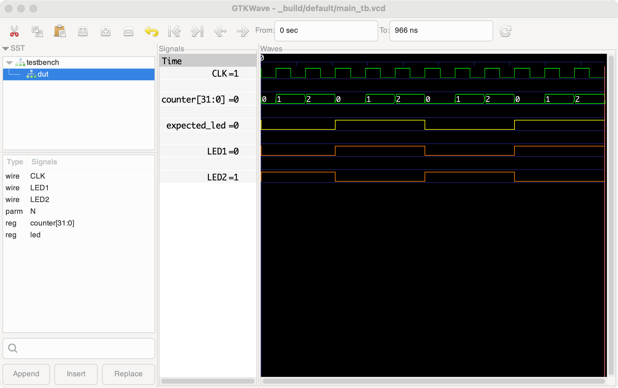
To simulate the design, we use the command apio sim, which runs a simulation of the testbench and shows its results in a graphical GTKWAVE window. The main_tb.gtkw contains the GTKWAVE configuration, and you should save it each time you make changes in GTKWAVE that you want to keep.
For more information about
apio sim, typeapio sim -h.
project$ apio sim

Step 5: Run the project tests
The command apio test runs all the testbenches it finds in the project in batch mode without a graphical view like apio sim. The command fails if any of the testbenches has an error or exits with the $fatal function, typically due to a failing assertion.
For more information about
apio test, typeapio test -h.
project$ apio test
Testbench main_tb.v
...
main_tb.v:45: $finish called at 966000 (1ps)
Step 6: Program the FPGA board
In this step, we build the project if needed and upload it to the FPGA board. With some systems and boards, this requires driver installation using the apio drivers install command, while others work out of the box. To test if the board is accessible, we will try to list it with the apio devices command. Since Alhambra-ii uses plain USB rather than a serial port, we will try to list it using the command apio devices usb.
project$ apio devices usb
USB Devices
┌───────────┬─────────┬──────────────┬───────────────────┬────────────┬─────────┐
│ VID:PID │ BUS:DEV │ MANUFACTURER │ DESCRIPTION │ SERIAL-NUM │ TYPE │
├───────────┼─────────┼──────────────┼───────────────────┼────────────┼─────────┤
│ 0403:6010 │ 0:3 │ AlhambraBits │ Alhambra II v1.0A │ │ FT2232H │
└───────────┴─────────┴──────────────┴───────────────────┴────────────┴─────────┘
Found 1 USB device
We are in luck; the device's manufacturer and description strings are listed correctly, which means that the device is accessible to Apio and doesn't require an additional driver. We are ready to program the FPGA.
project$ apio upload
...
Selecting USB device:
- FILTER [VID=0403, PID=6010, REGEX="^Alhambra II.*"]
- DEVICE [0403:6010, 0:3], [AlhambraBits] [Alhambra II v1.0A] []
...
Erasing: [==================================================] 100.00%
Writing: [==================================================] 100.00%
Reading: [==================================================] 100.00%
Done
The example now runs on the FPGA board, and two LEDs should be flashing alternately.
This concludes the Apio quick start guide, we suggest continuing to the Video tutorial or go ahead and start your own Apio project.